Nometre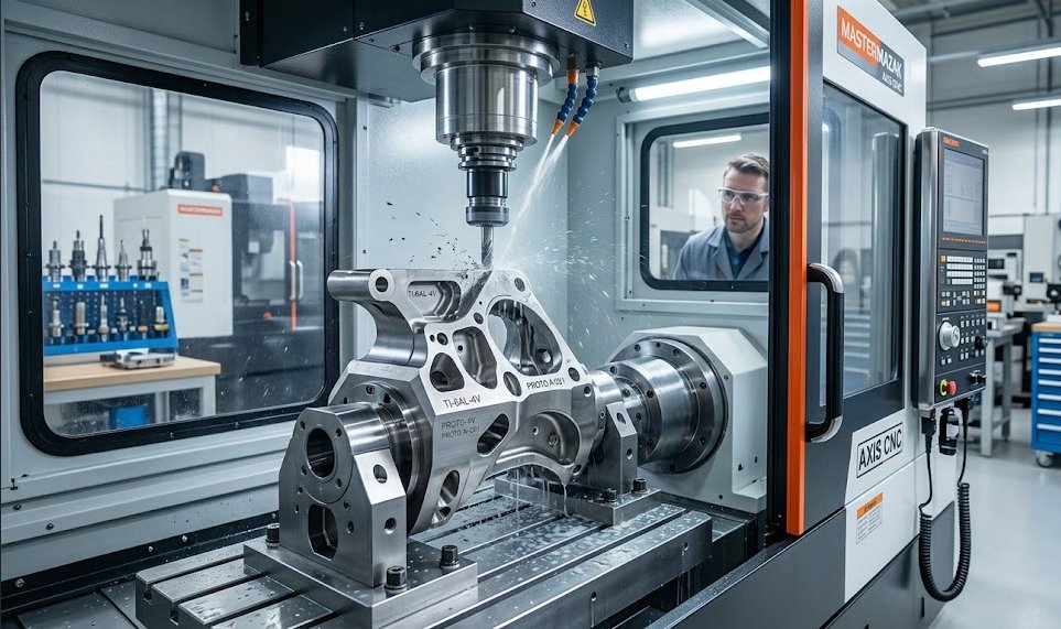
Aerospace prototypes often carry high expectations because the eventual hardware may face demanding loads, temperature changes, vibration, corrosion, or strict assembly interfaces. Yet early development still benefits from disciplined simplification. When using CNC machining, the best prototype drawing separates flight-critical or test-critical features from geometry that only supports handling or packaging. CSMolding lists aerospace among its industry areas and provides multi-axis machining for metals and engineering plastics.
Prototype purpose should drive material and inspection
An aerodynamic form model, a fit-check bracket, and a load-bearing test article do not need the same material pedigree or inspection depth. If the prototype will carry representative loads, use material and heat-treatment conditions that make the test meaningful. If it exists only to confirm installation space, a more economical stock may be appropriate.
Likewise, inspection should follow risk. Critical hole patterns, bearing interfaces, sealing surfaces, and datums can receive detailed dimensional verification while nonfunctional exterior surfaces follow a general tolerance. This concentrates time where a deviation would actually invalidate the test.
Multi-axis access can simplify complex parts
Aerospace components frequently combine angled faces, pockets, ribs, bores, and closely related features on several sides. Four- or five-axis machining can reduce the number of times a part is removed and re-fixtured, which may help maintain relationships among features. It can also allow shorter tool reach on angled surfaces.
However, complex capability does not eliminate DFM. Deep narrow pockets, thin ribs, inaccessible internal corners, and extreme aspect ratios still deserve scrutiny. A slightly larger corner radius or a redesigned relief can improve tool rigidity without changing function.
Keep configuration control as rigorous as geometry
Fast iteration creates its own risk: machining the wrong revision. Use clear part numbers, revision identifiers, material callouts, and drawing dates. If the prototype departs from the intended production design, document the deviation so test results are not later misapplied.
CSMolding’s stated workflow includes DFM review and dimensional/tolerance inspection during manufacturing. For an aerospace development team, that supplier feedback is most useful when the engineering package already explains which characteristics matter and why. Precision is not achieved by making every number tiny; it comes from controlling the right relationships, testing the correct configuration, and preserving evidence that connects the physical part to the engineering decision.


 Anastasiya Yurkevich